
Why?
Given my low income and my mechanical ability, and the relatively high cost of imported goods, I decided to build my own buggy. Having access to the Stunt Kites II (That Book again!) I based my buggy largely on their simple buggy design. Sadly, the books plans for the buggy are not complete and you have to guess some of the sizes and angles.
[box type=”alert” style=”rounded” border=”full”]Editor’s Note: Please note, the files in this article are no longer available with the following links and have not come up in any of our Google searches – if we’re able to locate them at some point, we will make every effort to update the links.[/box]I started by doing my own dimensioned drawing using TurboCAD. You can get a copy of that drawing from my web page in Hewlett Packard plotter language (HPGL) format. Most drawing programs, and even some word processors, will read that file format, though not all will print it to scale the way a CAD program will.
Mainframe
 The design is simple, a 1 meter back axle, 2 side pieces of 728mm long (take care with the chamfers for the joints), two 5x25x120 metal plates for the fork mounting make up the main frame. The pipes are welded into a triangle, leaving space at the apex for the mounting plates and the steering tube. I clamped the whoel lot together using G-Clamps and then welded it. If you don’t leav enough space, inserting the steering tube becomes difficult. The mounting plates are welded on at 33 degrees angle. The have a 6mm hole 15mm from each end (clamp them together and drill both at the same time) Later, drill matching holes in the steering tube to take 6mm bolts. 2 or 3 sets of holes will give you enough adjustment options, since where you first put it is seldom exactly right!
Front Fork
 The front fork is made of 2 pieces 350mm long (or whatever will fit your wheels), 2 pieces long enough to span your front wheel (mine is 120mm between inside faces, simply add twice your pipe size to that for the proper lengths), and two pieces 200mm long for the foot pegs. I used 19mm square tubing with 1.6mm wall thickness for everything except the steering tube, that is 38mm square. Note that I added two seat side tubes as an afterthought for sideways support, while the book makes a fancier seat instead. After making the rest of the frame, position two pipes about 50mm either side of your bum and mark them off, cut and weld them on firmly. All my welds are done using the 50amp setting with 2mm standard steel rods. I weld all mating faces thoroughly for strength. Your welder may work better at other settings. Be careful, the 1.6mm tubing burns through easily, so practise on some scraps before starting.
 Everything is non critical so long as it is near to what is shown in the drawing, and your wheels fit (don’t use wheels bigger than 16 inch diameter, or smaller than 12 inch). You can make the axle wider or narrower to adjust stability, you can change the steering angle to adjust steering response (straight up provides the most response, not good for speeds higher than 10km/h, more angled provides a slower response, good for high speed).
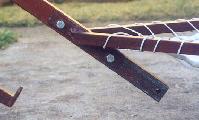 My steering angle is 33 degrees, and provides good turning ability AND good stability at speed. To weld the pieces to this angle I printed a fullsize closeup of the mounting plates and used that as a template for clamping the pieces prior to welding.
Wheels
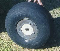
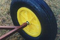
Initially I was going to build wheels, having been given some old 16inch Cessna airplane casings. This proved to be a lot of work which needs a large metalworking lathe. I asked a friend to mount bearings for me after I had turned laminated wood hubs to size. This proved to be a problem, since the friend is not a buggier and is very busy running his own business, so I ordered wheels from Dave Skinner of ‘The Kite Shop’. They are molded plastic hubs with 16×4 tires and come with no bearings. I again approached my friend, since the hubs need boring out for the bearings. I removed the tires and tubes and he fitted the bearings (sealed ball bearings from SKF) without trouble. The bearings have a 12mm internal diameter, to fit 12mm stainless steel bolts as axles. The front axle is a piece of 12mm stainless threaded at each end to take standard nuts. Since the bearing faces are less than 100mm apart, we used 100mm bolts and fitted a spacer. This also allows flexibility, in that fitting a different wheel is simply a matter of changing the spacer.
My advice is to buy wheels in as complete a form as you can get them, since this reduces the amount of engineering work involved.
Engineering
 While the welding is easy to do with a home arcwelder, and all cutting can be done with a hacksaw in your backyard, there are certain pieces which need to be engineered properly. These pieces include:
- the inserts in each end of the back axle tube that the wheel axles thread into
- the steering head Vescanite bearings (nice to have in Vescanite, nylon would also work)
If one uses a larger tubing for the rear axle, it would be possible to weld some standard steel nuts in place of machined inserts. My machined inserts are bigger than the inside of the tube by about 1.5mm and with a coned end they are hammered in and then welded. I recommend using a larger tube for the back axle.
The steering head is simply a piece of 40mm water pipe with the Vescanite bearings in each end. The Vescanite is drilled for a 12mm bolt. The pipe is 80mm long, and a stock 12mm stainless bolt fits through the fork with space for two locknuts at the top.
The Seat
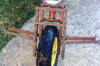
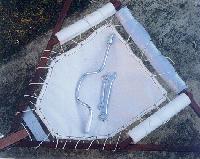 Not shown in the drawings, but the foto at right shows it clearly. The seat is a piece of strong nylon cloth with a 20mm hem around all edges such that the final size is some 30mm smaller than the frame, all around. Insert in the hem a piece of 3mm braided nylon rope and tie it off slighly small. Now melt holes every 50mm through the hem on the seat side of the rope with a soldering iron. A piece of 3mm braided nylon is now laced around the frame and through these holes and tied off. There is no need to leave slack, since the seat will stretch with use and you’ll want to tighten it now and then by drawing the lacing rope tighter. Along the back of the seat, around the rear axle, you need to wrap at least 20mm of hard foam rubber (I used blue hiking mattress 10mm thick, wound twice. The side tube pads shown in the foto are ex my daughters BMX bicycles). The lacing goes around this. trust me, you will only buggy once without padding. An alternative to this method is to make a padded backrest which covers the axle and provides lumbar support. I will be doing this soon and will make the details avialable on my web pages.
As you can see from the foto right above, I have padded the side tubes too. Since this foto was taken I buggied quite a bit and found that the ends of the seat side tubes bruised my thighs. To fix this, I sawed the inside top corners off and filled the end with wood plugs to prevent any chance of catching on the ends, and then shifted the padding forward so it covers the sidetube/frame joint. With this arrangement I had no bruises after several hours of buggying.
Also visible in the seat image is an aluminium plate just behind the downtube joint. This was put on as a way to assist assembly since I’d welded the frame slightly narrow and inserting the pipe against the spring of the frame was a hassle. I have since removed the aluminium plate and adjusted the frame by making saw cuts on each angle tube just forward of the side tube attachments, allowing the tubes to bend outwards. After sawing, I clamped the downtube in the headplates and welded the saw cuts closed again. Now the headplate gap is exact and inserting the downtube requires no effort. These rewelded bits are now covered by the shifted side pads.
So that’s it, pump the tires and ride! My buggy has a short turning radius, is comfortable, cheap to build (except the wheels) and since I can remove the wheels I can pack it flat in my car (hatchback) and leave room for a lot of other stuff. I carry a set of spanners which include a 6 and a 19mm flat spanner, 6 and 19mm sockets, and a speed wrench handle (for the sockets) for assembling the buggy onsite. The speedwrench is a must have. You can see the tools int he seat picture above right.
Cost
The big issue! I figure my buggy cost me around R600 (about US$100 in August 1998), which excludes paying my engineer friend for his time and materials. That could push the price up to around R900. New PL/Flexifoil etc buggies are in the region of R1500 (more as the rand/dollar falls).
The choice is yours….
You can download the drawings as a zipped set of GIF files, or as a zipped HPGL plot file
David